The Functional Structure of a Plastic Mold
A comprehensive guide to the components and systems that make up a high-performance plastic mold, essential for efficient and precise injection molding processes.
A plastic mold is a sophisticated tool used in the injection molding process to shape molten plastic into desired forms. The efficiency, precision, and durability of a plastic mold directly impact the quality of the final plastic parts, production cycle times, and overall manufacturing costs. Understanding the intricate structure of a plastic mold is essential for engineers, designers, and manufacturers involved in plastic part production.
The structure of a plastic mold is carefully engineered to perform multiple functions simultaneously during the injection molding cycle. From guiding molten plastic into the mold cavity to cooling the material, ejecting the finished part, and ensuring proper alignment during each cycle, every component of a plastic mold plays a critical role in the manufacturing process.
This detailed guide explores the primary functional systems that constitute a modern plastic mold, examining their components, purposes, and how they work together to produce high-quality plastic parts consistently.
The Heart of the Plastic Mold: Forming Components
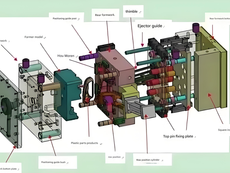
The molding section represents the core of any plastic mold, as it directly shapes the plastic material into the desired product form. This critical part of the plastic mold consists of components that form the mold cavity, where the molten plastic cools and solidifies into the final part geometry.
The primary components of the molding section include型腔 (cavities), 型芯 (cores), 成型 (molding inserts), 成型环 (molding rings), and 镶块 (insert blocks) — all parts that come into direct contact with the molten plastic during the injection process. These components must be manufactured with extreme precision to ensure the final plastic parts meet dimensional requirements and surface finish specifications.
In a typical plastic mold, the cavity is the female part of the mold that forms the outer surface of the plastic part, while the core is the male component that shapes the inner surfaces. For complex part geometries, multiple cores and cavities may be integrated into a single plastic mold to produce multiple parts in a single molding cycle or to create intricate features.
Molding inserts and insert blocks are often used in a plastic mold to create specific features or to facilitate easier maintenance and replacement of high-wear areas. These interchangeable components allow for modifications to part design without rebuilding the entire plastic mold, significantly reducing tooling costs for design iterations.
The materials used for these forming components are carefully selected based on the plastic material being processed, production volume requirements, and part quality specifications. Common materials include various tool steels such as P20, H13, and S7, which offer excellent wear resistance, thermal stability, and machinability — all essential properties for withstanding the harsh conditions inside a plastic mold during production.
Key Characteristics of Molding Components
- Extremely tight dimensional tolerances (often ±0.001mm)
- High surface finish quality (mirror polish for optical parts)
- Resistance to thermal cycling and wear
- Compatibility with the plastic material being processed
The Plastic Flow Path: Gating and Runners
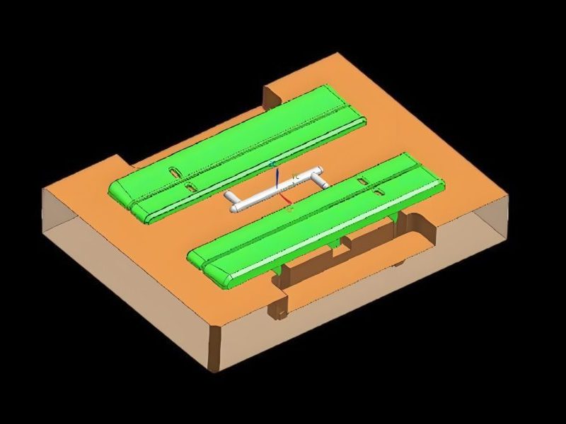
The gating system in a plastic mold is the network of channels that delivers molten plastic from the injection molding machine's nozzle to the mold cavity. This critical system in the plastic mold controls how the material fills the cavity, which directly affects part quality, cycle time, and material usage.
A well-designed gating system ensures that molten plastic fills the cavity uniformly, without creating excessive pressure drops, air traps, or weld lines. The design of this system in a plastic mold depends on numerous factors, including part geometry, plastic material properties, and production requirements.
The basic components of a standard gating system in a plastic mold include:
Main Components of a Plastic Mold Gating System
-
Sprue (主流道): The primary channel that connects the injection machine nozzle to the rest of the system in the plastic mold, typically tapered to facilitate material flow and ejection of the sprue from the mold.
-
Runners (分流道): Secondary channels that distribute molten plastic from the sprue to multiple cavities in a multi-cavity plastic mold, designed to ensure balanced flow to all cavities.
-
Gates (浇口): The narrow opening through which plastic enters the cavity, controlling flow rate and pressure. Gate design in a plastic mold varies (edge, sprue, submarine, hot tip) based on part requirements.
-
Cold Slug Well (冷料穴): A reservoir at the end of the sprue or runner that collects the first, coolest plastic material, preventing it from entering the cavity and causing defects in the plastic mold.
In advanced plastic mold designs, hot runner systems may replace traditional cold runners. These systems keep the plastic molten in the runner system, eliminating runner waste and reducing cycle times. While more expensive initially, hot runner systems in a plastic mold can provide significant cost savings for high-volume production runs.
Gate Types
- • Edge Gate
- • Pin Point Gate
- • Submarine Gate
- • Fan Gate
- • Diaphragm Gate
Runner Design Considerations
- • Balanced Flow
- • Minimum Pressure Drop
- • Easy Ejection
- • Material Savings
- • Proper Venting
Precision Alignment: The Plastic Mold Guiding System
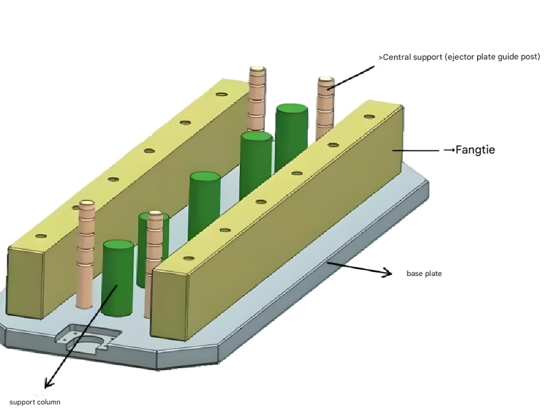
The guiding mechanism is an essential component of any plastic mold, responsible for ensuring precise alignment between the moving and stationary halves of the mold during each production cycle. This system guarantees that the mold closes accurately, maintains proper alignment during injection pressure, and opens consistently — all critical factors for producing high-quality parts and preventing damage to the plastic mold.
Without an effective guiding system, a plastic mold would suffer from misalignment during operation, leading to flash (excess plastic at the part edge), dimensional inaccuracies, and potentially catastrophic damage to the mold components. The guiding mechanism must withstand significant forces during mold closing and injection, requiring robust design and high-quality materials.
The primary components of a typical guiding mechanism in a plastic mold include:
Guide Pins (导柱)
These are cylindrical precision components, usually made from hardened steel, that extend from one mold plate and fit into corresponding guide bushings or holes in another plate. In a plastic mold, guide pins ensure accurate alignment in the horizontal plane.
Guide Bushings (导套)
These precision sleeves are mounted in mold plates to receive the guide pins, reducing friction and wear between moving parts. In high-performance plastic molds, bushings may be made from self-lubricating materials or include lubrication channels.
Guide Holes
In some plastic mold designs, precision-machined holes in the mold plates replace guide bushings. These are typically used in less demanding applications or where space constraints require a more compact design.
Locating Tapers (定位锥面)
Also known as "虎口" (tiger's mouth) in some terminology, these conical surfaces provide additional alignment precision, especially for large plastic molds or those requiring extremely tight tolerances. They help prevent lateral movement during injection pressure.
The design of the guiding mechanism in a plastic mold depends on factors such as mold size, part precision requirements, and production volume. Larger plastic molds typically require more guide pins strategically positioned to ensure uniform alignment. High-volume production molds often feature hardened and ground guiding components to withstand millions of cycles without excessive wear.
Guiding System Design Principles
Part Removal: The Plastic Mold Ejection System
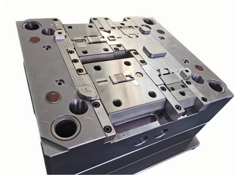
After the plastic material has cooled and solidified in the mold cavity, the finished part must be reliably removed from the plastic mold. This critical function is performed by the ejection mechanism, a system of components designed to apply the necessary force to separate the part from the mold surfaces without causing damage to either the part or the plastic mold itself.
The design of the ejection system in a plastic mold depends on numerous factors, including part geometry, material properties, surface finish requirements, and production volume. A well-designed ejection system ensures efficient, consistent part removal while maintaining part quality and minimizing cycle time in the plastic mold.
The ejection mechanism in a typical plastic mold consists of several key components working together:
Ejector Pins (顶杆)
The most common ejection components, these are cylindrical pins that push against the part to eject it from the plastic mold. They are available in various diameters and lengths, with different tip configurations for specific applications.
Ejector Sleeves (顶管)
Hollow cylindrical sleeves used to eject parts with cylindrical features, providing uniform ejection force around a core in the plastic mold. They are particularly useful for parts with bosses or other protruding features.
Ejector Plates (推板)
Flat plates that make contact with larger surface areas of the part, providing uniform ejection force. They are often used for thin-walled parts or components with delicate features in a plastic mold.
Ejector Retainer Plates (顶杆固定板)
Plates that secure the ejection components (pins, sleeves, etc.) in position within the plastic mold. They work in conjunction with the ejector plates to transmit force from the mold machine's ejection system.
Additional Ejection Components
-
Return Pins (复位杆): These components reset the ejection system to its original position after part removal, ensuring proper closure of the plastic mold for the next cycle.
-
Sprue Pullers (拉料杆): These specialized pins or components retain the sprue and runner system as the mold opens, ensuring they are ejected along with the part from the plastic mold.
-
Ejection Springs: Used in some plastic mold designs to provide initial ejection force or to assist in the ejection process, particularly in molds with complex ejection requirements.
Ejection system design must carefully consider the location of ejection components to avoid visible marks on cosmetic surfaces of the part. In a plastic mold producing parts with high cosmetic requirements, ejection may be located on non-visible surfaces or designed to minimize witness marks. The ejection force must be sufficient to overcome the part's shrinkage onto cores and any surface tension between the part and mold surfaces, but not so excessive as to cause part deformation.
Ejection System Design Considerations
Complex Geometries: Side Action in Plastic Mold Design
Many plastic parts require features such as undercuts, threads, holes, or projections that are not parallel to the mold's opening and closing direction. These features necessitate specialized mechanisms in the plastic mold that can move perpendicular or at an angle to the main mold opening direction. The侧向分型与抽芯机构 (side core-pulling mechanism) fulfills this critical function, allowing the production of complex geometries that would otherwise be impossible with a simple two-plate plastic mold.
The side core-pulling mechanism in a plastic mold operates by retracting (pulling) side cores or splitting (parting) side cavities away from the part before ejection, and then returning them to their original position for the next molding cycle. This additional movement adds complexity to the plastic mold design but enables the production of highly functional plastic parts with intricate features.
There are several types of side core-pulling mechanisms used in plastic mold design, each with its own advantages and applications:
Angle Pin Mechanism (斜导柱)
The most common side core-pulling system in plastic molds, utilizing a diagonal pin fixed to the stationary half of the mold. As the mold opens, the angle pin engages with a slot in the side core, forcing it to move laterally and withdraw from the part.
Advantages: Simple design, reliable operation, cost-effective for many applications in a plastic mold.
Bend Pin Mechanism (弯销)
Similar to the angle pin design but using a rectangular cross-section pin that provides greater strength. This design is often used in plastic molds requiring longer core pulls or where higher forces are involved.
Advantages: Higher rigidity, better force transmission, suitable for larger side cores in a plastic mold.
Angle Slide Mechanism (斜滑块)
Utilizes a sliding block that moves along an angled surface as the plastic mold opens. This design is often used for large undercuts or when the side action needs to cover a large area of the part.
Advantages: Provides stable movement, suitable for large undercuts, can incorporate multiple core features in a single slide.
For more complex plastic mold applications, additional components may be integrated into the side core-pulling mechanism:
-
Locks or Clamps (紧块): These components secure the side cores in their extended position during the injection phase of the plastic mold cycle, preventing movement under injection pressure.
-
Gear and Rack Mechanisms: Used in plastic molds requiring long core pulls or rotational movement (such as for threading), these systems convert linear motion to rotational motion.
-
Springs and Hydraulic/Pneumatic Cylinders: These provide additional force or control for side core movement in specialized plastic mold applications, offering greater flexibility in timing and force.
The design of side core-pulling mechanisms requires careful consideration of factors such as undercut size, required movement, available space in the plastic mold, and production volume. Each additional side action increases the complexity, cost, and potential maintenance requirements of the plastic mold, but enables the production of more functional and complex plastic parts.
Common Applications for Side Actions
- • Threaded features on plastic parts
- • Holes perpendicular to mold opening direction
- • Undercuts for snap-fit assemblies
- • Protrusions and recesses on vertical surfaces
- • Complex geometric features requiring multi-axis molding
Design Challenges with Side Cores
- • Maintaining part dimensional accuracy
- • Ensuring proper alignment during core movement
- • Managing increased cycle time
- • Providing adequate cooling for side cores
- • Preventing core collision during operation
Thermal Management: Plastic Mold Cooling and Heating
Temperature control is a critical aspect of plastic mold performance, directly impacting part quality, cycle time, and production efficiency. The cooling and heating system in a plastic mold regulates the temperature of the mold surfaces, ensuring proper plastic flow, uniform cooling, and consistent part dimensions. For certain plastic materials and part designs, precise heating may be required in specific areas of the plastic mold to facilitate proper filling or to prevent premature freezing of the molten plastic.
The majority of injection molding applications require effective cooling of the plastic mold to solidify the molten plastic quickly and uniformly. The cooling system reduces the time required for the plastic to reach a sufficiently low temperature for ejection, directly reducing cycle time and increasing production output.
A well-designed cooling system in a plastic mold provides:
The primary components of a plastic mold cooling system include:
Cooling Channels (冷却水孔)
These are precision-drilled or milled passages in the plastic mold plates through which a cooling medium (typically water) circulates. The layout, diameter, and spacing of these channels are critical factors in determining cooling efficiency.
Cooling Manifolds
These components distribute the cooling medium to multiple cooling channels in the plastic mold, ensuring balanced flow and consistent temperature control across all areas of the mold.
Cooling Fittings
These connectors attach the plastic mold to the molding machine's cooling system, allowing the flow of cooling medium into and out of the mold. Quick-connect fittings are commonly used for efficient mold changes.
In some plastic mold applications, heating systems are required instead of or in addition to cooling. This is particularly true for high-temperature plastics or when specific mold areas need to maintain elevated temperatures to ensure proper filling of complex part geometries.
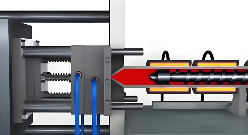
Heating systems in a plastic mold may utilize electric heating elements, hot oil circulation, or steam. These systems are often used in hot runner plastic molds to maintain molten plastic in the runner system while the mold cavity is cooled. Precise temperature control is essential, with modern plastic molds often incorporating thermocouples and proportional-integral-derivative (PID) controllers to maintain exact temperature settings.
Cooling System Design Best Practices
Position cooling channels as close to the cavity surface as possible, maintaining uniform distance from the part throughout the plastic mold.
Use parallel cooling circuits with balanced flow to ensure consistent temperatures across all areas of the plastic mold.
Implement baffles or bubblers in thick sections of the part to improve cooling efficiency in these difficult-to-cool areas of the plastic mold.
Ensure adequate water flow rate to achieve turbulent flow in cooling channels, which provides significantly better heat transfer than laminar flow.
Air Management: The Plastic Mold Ventilation System
During the injection phase of the molding cycle, the molten plastic enters the cavity and displaces air and gases that must be properly exhausted from the plastic mold. The ventilation system (排气系统) is responsible for removing these gases to prevent defects in the molded part and ensure complete filling of the cavity. Without adequate ventilation, a plastic mold can produce parts with burns, voids, incomplete filling, or other quality issues that compromise part functionality and appearance.
The gases that need to be vented from a plastic mold include ambient air in the cavity, volatile gases released from the molten plastic, and potentially combustion by-products if the plastic is overheated. These gases must be allowed to escape as the plastic fills the cavity, as trapped gases can reach extremely high temperatures under compression, causing material degradation and surface burns on the part.
The primary components of a plastic mold ventilation system include:
Vent Grooves (排气槽)
These are shallow channels machined into the mold at the parting line, along the last areas to fill with plastic. In a properly designed plastic mold, these grooves allow air to escape while preventing molten plastic from flowing out of the cavity.
The depth of these grooves is critical — typically between 0.02mm and 0.1mm (0.0008" to 0.004") depending on the plastic material's viscosity and flow characteristics in the plastic mold.
Parting Line Vents
These are the most common type of ventilation in a plastic mold, utilizing the natural gap between the moving and stationary mold halves. By carefully controlling the flatness and parallelism of the mold plates, a uniform micro-gap is created that allows air to escape while retaining the molten plastic.
配合间隙 (Fitting Clearances)
In many cases, the intentional clearance between moving components in the plastic mold (such as between ejector pins and their guide holes, or between sliding cores and their guides) serves as effective ventilation. These clearances provide additional paths for air to escape from difficult-to-reach areas of the cavity.
For specialized applications, a plastic mold may incorporate additional ventilation features:
-
Vent Pins: These are porous metal pins or specially designed components inserted into deep recesses or thick sections of the plastic mold where conventional vents are ineffective.
-
Vacuum Ventilation: In some high-precision plastic molds, a vacuum system is connected to the ventilation channels to actively remove air from the cavity before and during injection.
-
Submarine Vents: These are vents located in ejector pins or other moving components, allowing ventilation in areas that are not accessible from the main parting line of the plastic mold.
The design of the ventilation system in a plastic mold requires careful analysis of the filling pattern, with vents strategically placed at the last points to fill in each cavity. Proper venting is essential for achieving complete cavity filling, reducing cycle time, and preventing gas-related defects. However, vents must be carefully designed to avoid creating flash or burrs on the part, which would require secondary processing. In production, the ventilation system of a plastic mold may require periodic cleaning to remove plastic residue that can block the vents over time, ensuring consistent part quality throughout the mold's service life.
Signs of Inadequate Ventilation
- Burn marks on the part surface, particularly in deep recesses
- Incomplete filling of the cavity, especially in thin sections
- Voids or bubbles in thick sections of the molded part
- Excessive injection pressure required to fill the mold
- Jetting or flow lines on the part surface
Vent Design Considerations
The Integrated Plastic Mold System
A modern plastic mold is a sophisticated integration of multiple systems working in harmony to produce high-quality plastic parts efficiently. From the precision forming surfaces of the molding section to the complex movements of side core-pulling mechanisms, each component and system plays a vital role in the plastic mold's overall performance.
Understanding the functional structure of a plastic mold is essential for optimizing part design, troubleshooting production issues, and ensuring efficient, cost-effective manufacturing. As plastic materials and molding technologies continue to evolve, so too do the design and capabilities of the modern plastic mold, enabling the production of increasingly complex and high-performance plastic components.
Learn more