Mold Parts Classification
Comprehensive guide to the functional structures and components of industrial molds, including the detailed breakdown of the injection mold systems.
Mold Industry Classification Standards
The manufacturing industry relies heavily on precision molds and dies to produce consistent, high-quality components. Proper classification of mold parts is essential for efficient production, maintenance, and replacement. This guide provides the most comprehensive breakdown of mold components, focusing on the injection mold systems, stamping dies, and their respective manufacturing processes.
Understanding the classification of these components ensures that manufacturers can source the correct parts, perform accurate maintenance, and optimize production processes. The injection mold represents a significant segment of the mold industry, with its own unique set of components and functional requirements.
Of manufacturing components use injection mold technology
Critical components in a standard injection mold
Reduction in defects with proper part classification
Plastic MoldInjection Mold Functional Structure & Components
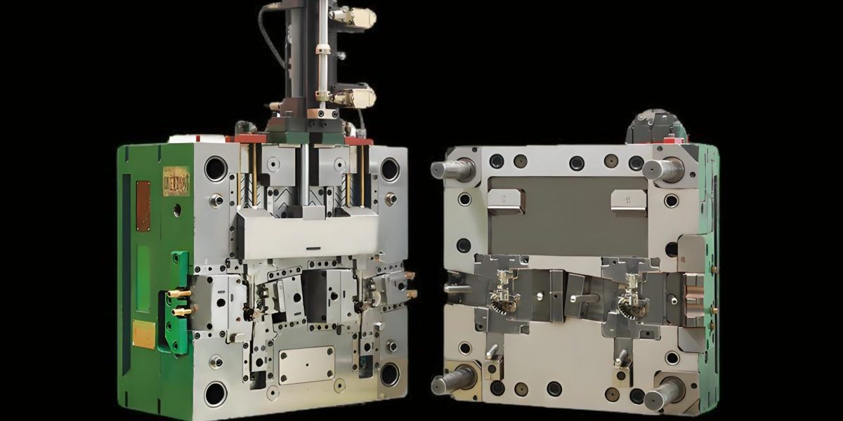
The injection mold is a complex assembly of precision components designed to shape molten plastic into specific forms. The functionality of an injection mold depends on the harmonious interaction of its various systems, each contributing to the overall molding process. From clamping to ejection, every component in an injection mold plays a critical role in producing high-quality plastic parts.
Functional Structure of Injection Molds
An injection mold consists of several key functional systems that work together to transform raw plastic material into finished products. These systems are engineered to withstand high pressures, temperatures, and repeated cycles while maintaining precision and consistency.
-
Clamping System: Secures mold halves during injection and cooling
-
Injection System: Channels molten plastic into the mold cavity
-
Cavity and Core System: Defines the final shape of the plastic part
-
Cooling System: Regulates temperature for proper solidification
-
Ejection System: Removes finished parts from the mold
-
Guiding System: Ensures precise alignment of mold halves
Injection Mold System Interaction
The efficiency of an injection mold depends on how well these systems coordinate during each production cycle:
- Clamping system closes the mold with precise force
- Injection system delivers molten plastic into the cavity
- Cooling system activates to solidify the plastic
- Clamping system releases after proper cooling time
- Ejection system removes the finished part
- Cycle repeats with new material injection
A typical injection mold can complete 50,000 to 1,000,000 cycles before requiring major maintenance, depending on material and design.
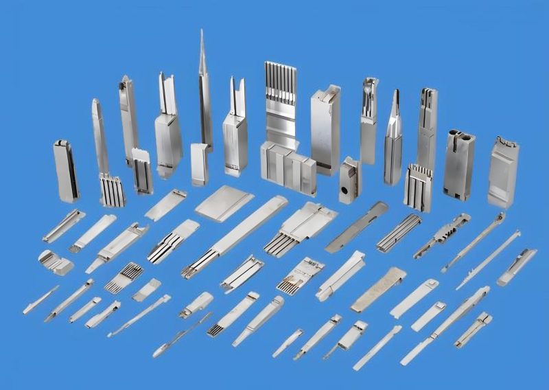
Components of an Injection Mold
Each injection mold comprises numerous precision components, each with specific functions that contribute to the overall performance. These components are categorized based on their role within the mold's functional systems, ensuring that every aspect of the injection molding process is controlled and optimized.
Cavity & Core Components
- Cavity Plate - Forms external part geometry
- Core Insert - Creates internal part features
- Cavity Insert - Replaceable molding surface
- Core Pin - Forms holes and recesses
- Slider - Creates undercuts in complex parts
- Lifter - Extracts parts with undercut features
Clamping Components
- Clamping Plate - Secures mold to machine
- Support Plate - Reinforces mold structure
- Spacer Block - Creates ejection space
- Tie Bar - Maintains mold alignment
- Clamping Screw - Secures mold components
- Locating Ring - Aligns mold with injection unit
Ejection Components
- Ejector Plate - Activates ejection system
- Ejector Pin - Directly pushes part from mold
- Ejector Sleeve - Releases around cylindrical features
- Return Pin - Resets ejection system
- Ejector Guide - Ensures smooth ejection movement
- Sprue Puller - Removes sprue from runner system
Cooling Components
- Cooling Channel - Circulates temperature-controlled fluid
- Cooling Pin - Provides localized cooling
- Water Manifold - Distributes cooling fluid
- O-Ring - Seals cooling system connections
- Plug - Closes cooling channel ends
- Thermocouple - Monitors mold temperature
Gating Components
- Sprue Bushing - Connects to injection unit
- Runner - Distributes plastic to cavities
- Gate - Controls plastic flow into cavity
- Hot Runner Manifold - Maintains melt temperature
- Nozzle - Delivers plastic to each cavity
- Valve Gate - Controls flow timing in hot runners
Guiding Components
- Guide Pin - Aligns moving and fixed halves
- Guide Bushing - Houses and guides guide pins
- Leader Pin - Initial alignment during closing
- Leader Bushing - Guides leader pins
- Locator Pin - Precise positioning of inserts
- Anti-Rotation Pin - Prevents component rotation
Material Selection for Injection Mold Components
The choice of materials for injection mold components directly impacts performance, durability, and cost. Different components within an injection mold require specific material properties based on their function, exposure to heat, pressure, and wear factors.
| Component Type | Common Materials | Key Properties | Typical Hardness |
|---|---|---|---|
| Cavity & Core Inserts | P20, H13, S136, 718H | Wear resistance, polishability, corrosion resistance | 30-50 HRC |
| Ejector Pins | SKD61, H13, 420 stainless | High strength, toughness, wear resistance | 45-55 HRC |
| Guide Pins & Bushings | SUJ2, 440C stainless | High hardness, low friction, wear resistance | 58-62 HRC |
| Plates | S50C, 45# steel, aluminum | Strength, machinability, cost-effectiveness | 15-25 HRC |
| Hot Runner Components | H13, 316 stainless | Heat resistance, corrosion resistance | 40-48 HRC |
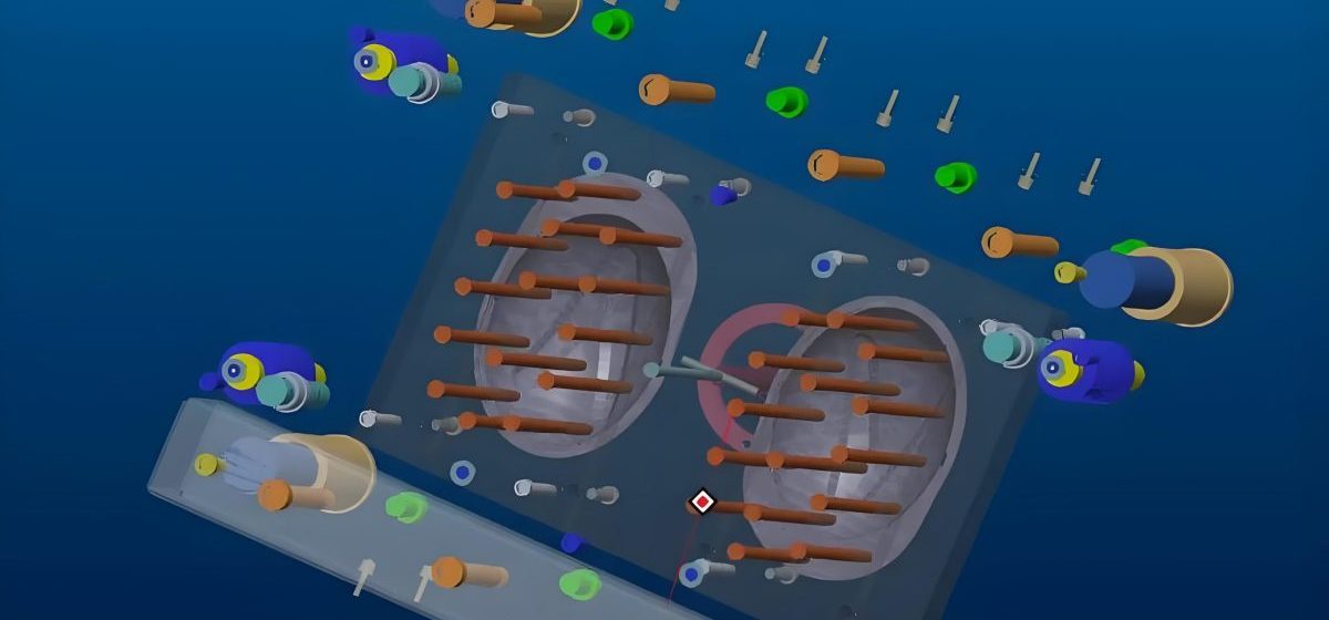
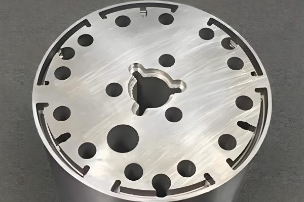
Cross-sectional view of a typical injection mold showing the cavity, core, cooling channels, and ejection system components
Stamping Die Functional Structure & Components
Stamping dies are specialized tools used to shape and form metal sheets through various processes including cutting, bending, and drawing. Unlike the injection mold which works with molten materials, stamping dies operate through mechanical force applied to solid metal. The construction of stamping dies involves precision components designed to withstand high impact forces while maintaining dimensional accuracy.
Functional Structure of Stamping Dies
Mold Parts: Stamping dies are categorized based on their specific functions and the operations they perform. While an injection mold typically performs a single operation per cycle, stamping dies can be designed for progressive operations where metal undergoes multiple transformations in sequence.
Single-Station Dies
Perform one operation per press stroke, such as blanking, piercing, or bending. These dies are simpler in construction compared to progressive dies and are ideal for simple parts or low-volume production.
Progressive Dies
Feature multiple stations that perform different operations sequentially as the material strip advances through the die. Each station modifies the part until the final shape is achieved, allowing complex parts to be produced efficiently in high volumes.
Compound Dies
Perform multiple operations simultaneously in a single press stroke. These dies are capable of producing more complex parts than single-station dies while maintaining high precision and alignment between features.
Stamping Die Operational Sequence
-
1Material feeding into the die system
-
2Locating and positioning the material
-
3Performing the stamping operation (cutting, forming, etc.)
-
4Stripping the part from the tooling
-
5Ejecting or advancing the part to next station
Key Operational Parameters
- • Press force: 5-3000 tons depending on application
- • Stroke rate: 10-1200 strokes per minute
- • Material thickness: 0.05-12mm typical range
- • Tolerances: ±0.01mm achievable with precision dies
Components of Stamping Dies
Stamping die components are designed to withstand high impact forces and repeated cycles, much like the injection mold but with different mechanical requirements. These components can be broadly categorized into those that form the working surfaces and those that provide support, guidance, and actuation.
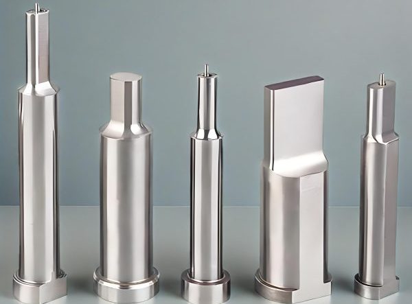
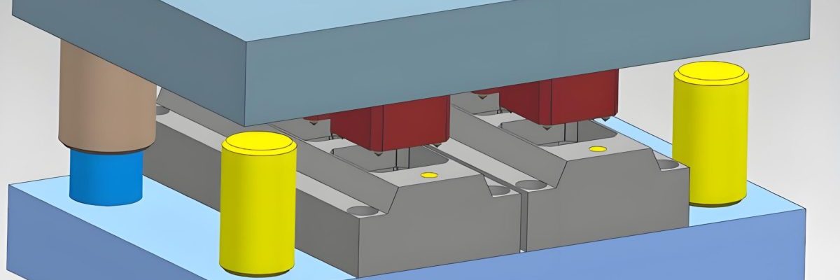
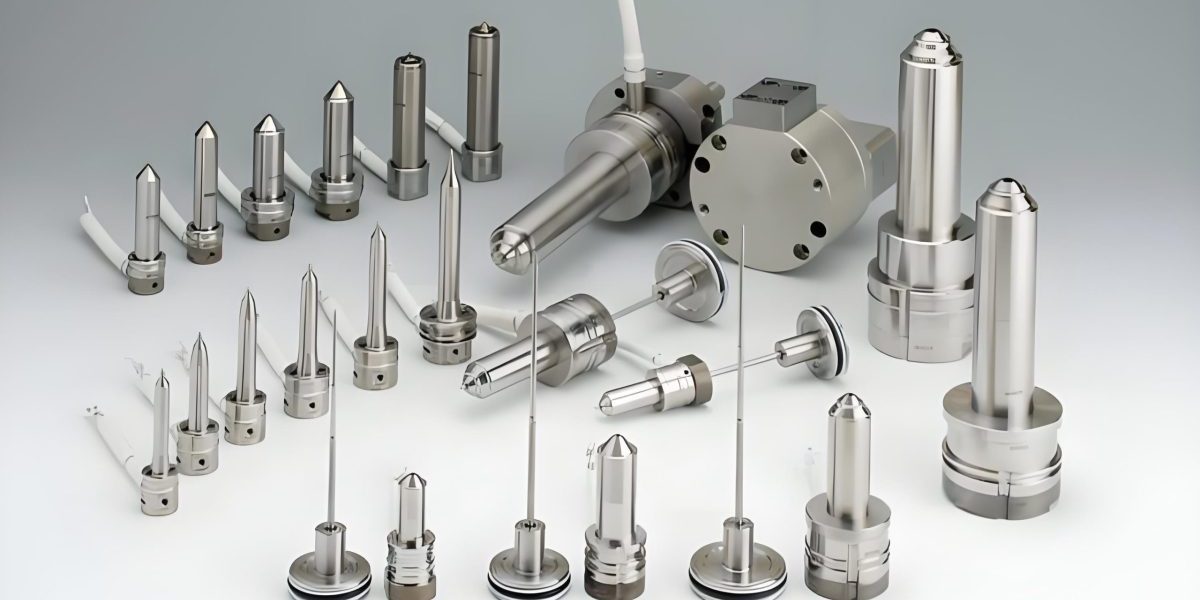
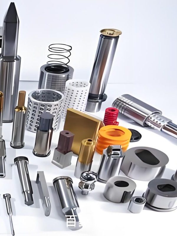
Critical working components of a stamping die: punches, dies, and strippers
Working Components
These components directly interact with the material being processed, shaping it into the desired form:
-
Punch: The moving component that contacts the material, creating holes or forming shapes
-
Die Block: The stationary component that works with the punch to shape material
-
Stripper Plate: Removes material from the punch after the operation
-
Blanking Die: Cuts flat shapes from sheet material
-
Forming Punch: Bends or shapes material without cutting
-
Piercing Punch: Creates holes in the material
-
Bending Die: Forms angles and bends in the material
Guide Components
- Guide Post - Aligns upper and lower die sections
- Guide Bushing - Guides and supports guide posts
- Ball Cage - Reduces friction between guides
- Die Set - Pre-assembled guide system
- Shoulder Guide Post - Provides positive stop
- Guide Rail - Guides material through die
Supporting Components
- Upper Die Base - Mounts to press ram
- Lower Die Base - Mounts to press bed
- Die Shoe - Protects die base from wear
- Padding Block - Adjusts height and supports
- Backing Plate - Reinforces punch holders
- Gripper - Feeds material through die
Actuating Components
- Ejector Pin - Removes parts from die cavity
- Spring - Provides return force for components
- Cam - Converts motion in progressive dies
- Lifter - Raises parts during ejection
- Stop Pin - Controls material feeding position
- Air Ejector - Uses compressed air for ejection
Progressive Die Station Configuration
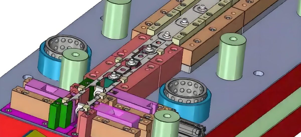
Progressive stamping die with multiple stations showing (1) piercing, (2) forming, (3) bending, and (4) blanking operations in sequence
Material Selection for Stamping Die Components
Stamping die materials must withstand high impact forces, abrasion, and occasional shock loading. Unlike the injection mold which primarily deals with thermal stresses, stamping dies require materials with high toughness and wear resistance.
| Component Type | Common Materials | Key Properties | Application Notes |
|---|---|---|---|
| Punches & Dies | D2, A2, S7, M2, carbide | High hardness, wear resistance, toughness | Carbide used for high-volume, abrasive materials |
| Stripper Plates | A36, 4140, D2 | Flatness, moderate wear resistance | Hardened versions for abrasive materials |
| Guide Components | SUJ2, 52100, 440C | High hardness, low friction, wear resistance | Often heat treated and precision ground |
| Die Bases | A36, 4140, cast iron | Strength, stability, machinability | Cast iron provides good damping properties |
| Ejection Components | 4140, 8620, S7 | Toughness, fatigue resistance | Heat treated for strength without brittleness |
Mold Part Manufacturing Classification
The manufacturing processes for mold components are critical to their performance and longevity. Both injection mold and stamping die components require precise manufacturing techniques to achieve the necessary tolerances and surface finishes. The classification of these manufacturing processes helps in selecting the appropriate method for each component based on its material, geometry, and performance requirements.
Primary Manufacturing Processes
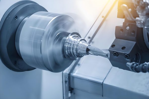
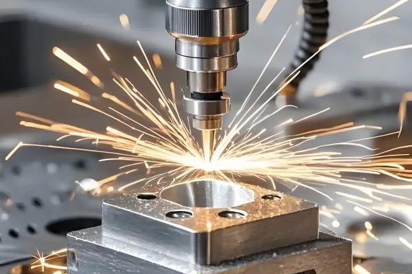
CNC Machining
Computer Numerical Control (CNC) machining is the backbone of mold component manufacturing, used extensively for both injection molding mold parts and stamping die parts. This process offers exceptional precision and repeatability.
- • Tolerances: ±0.001mm achievable
- • Surface finish: Up to Ra 0.02μm with proper techniques
- • Typical materials: All mold steels, aluminum, copper alloys
Electrical Discharge Machining (EDM)
EDM is essential for creating complex shapes and tight tolerances in hardened materials that would be difficult or impossible to machine with conventional methods, particularly valuable for injection mold cavities with intricate details.
- • Tolerances: ±0.0005mm achievable
- • Surface finish: Up to Ra 0.08μm
- • Ideal for: Complex geometries, hardened materials
Grinding
Grinding processes are used to achieve the highest precision dimensions and surface finishes on mold components. This is critical for injection mold surfaces that require high polish for cosmetic parts.
- • Tolerances: ±0.0001mm with precision grinding
- • Surface finish: Up to Ra 0.008μm with superfinishing
- • Applications: Flat surfaces, cylindrical components, guideways
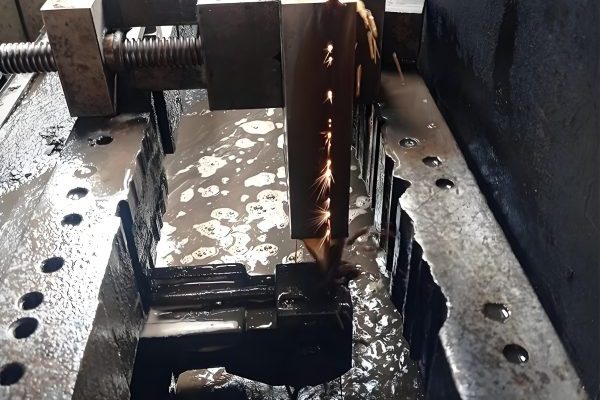
Wire EDM
Wire EDM uses a thin electrode wire to cut complex shapes with high precision. This process is particularly valuable for stamping die components and injection mold inserts with intricate profiles.
- • Tolerances: ±0.001mm
- • Typical wire diameter: 0.1-0.3mm
- • Ideal for: Complex 2D shapes, sharp corners, narrow slots
Secondary & Finishing Processes
After primary machining, mold components undergo various secondary and finishing processes to enhance their performance characteristics. These processes are crucial for both injection mold and stamping die components, ensuring they can withstand the demanding conditions of their intended applications.
Heat Treatment
Hardening, tempering, and annealing processes to achieve desired mechanical properties. Critical for punch and die components requiring wear resistance.
Surface Coating
Applications like PVD, CVD, and nitriding to improve wear resistance, reduce friction, and prevent corrosion in critical components.
Polishing
Progressive refinement of surface finish, essential for injection mold cavities that produce cosmetic plastic parts.
Assembly & Fitting
Precision fitting of components to ensure proper operation, including lapping and matching of critical mating surfaces.
Process Selection Decision Tree
The selection of manufacturing processes for mold components depends on various factors including material type, component geometry, required tolerances, and production volume. The following flowchart provides a decision framework for choosing the appropriate processes, whether for an injection mold or stamping die component.
Key Decision Factors
Material Hardness
Components with hardness above 40 HRC typically require EDM or grinding processes, while softer materials can be machined with conventional methods.
Geometry Complexity
Simple shapes are economical to produce with CNC machining, while complex internal features often require EDM techniques.
Tolerance Requirements
Tolerances tighter than ±0.005mm usually require secondary processes like grinding or lapping to achieve.
Surface Finish
Cosmetic surfaces, particularly in injection mold cavities, require progressive polishing up to mirror finishes.
Production Volume
High-volume production may justify specialized tooling or processes to reduce per-part costs.
Typical Process Sequence for Critical Components
- Rough machining (milling/turning)
- Heat treatment
- Stress relieving
- EDM (if complex geometry)
- Grinding (for flatness and precision)
- Finishing (polishing/coating)
- Inspection and quality control
Process Capability Comparison
Understanding the capabilities and limitations of each manufacturing process is essential for selecting the optimal method for producing injection mold and stamping die components. The following chart compares key performance metrics across different processes.
Comprehensive Mold Part Classification Summary
Proper classification of mold components and their manufacturing processes is fundamental to efficient production, quality control, and maintenance. Both injection mold and stamping die systems consist of numerous specialized components, each with unique functions and manufacturing requirements.
The injection mold relies on precise coordination of cavity, cooling, ejection, and gating systems to produce plastic parts, while stamping dies utilize punches, dies, and progressive stations to form metal components. Understanding the classification of these components and their manufacturing processes ensures optimal performance, longevity, and cost-effectiveness in production environments.